Related products
-
Sale!
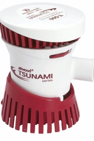
Tsunami 500 Bilge Pump (OEM)
Original price was: £23.44.£19.53Current price is: £19.53. -
Sale!
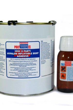
Hypalon (2990) 2 Part Adhesive – 1L tin & 40ml cure
Original price was: £58.06.£48.38Current price is: £48.38. -
Sale!
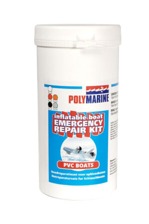
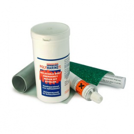
PVC Inflatable Boat Repair Kit – Grey
Original price was: £36.38.£30.32Current price is: £30.32. -
Sale!
Hypalon Inflatable Boat Repair Kit -Black
Original price was: £38.83.£32.36Current price is: £32.36. -
Sale!
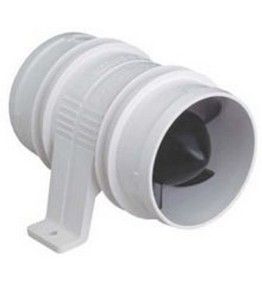
Water-resistant Bilge Blower 3″ (12v)
Original price was: £26.06.£21.72Current price is: £21.72. -
Sale!
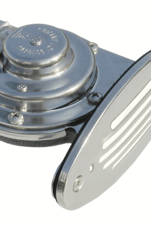
Mini Drop-In Horn c/w SS Grill – Low Pitch
Original price was: £64.02.£53.35Current price is: £53.35.
“A review from a customer who benefited from your product. Reviews can be a highly effective way of establishing credibility and increasing your company's reputation.”

Customer Name
“A review from a customer who benefited from your product. Reviews can be a highly effective way of establishing credibility and increasing your company's reputation.”
Customer Name
“A review from a customer who benefited from your product. Reviews can be a highly effective way of establishing credibility and increasing your company's reputation.”
Customer Name